Hbridge Stepper motor driver circuit. Download Scientific Diagram

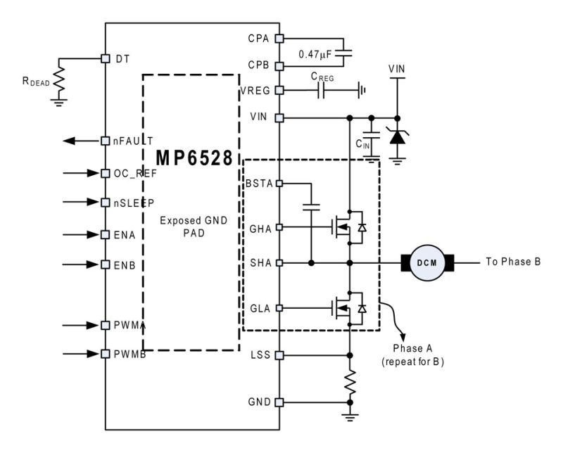
In the context of DC motor control, dead-time is a small amount of time inserted between the switching edges of PWM signals which drive switches on the same H-bridge leg (Figure 6). Figure 6. Dead-time between complementary PWM signals. Image used courtesy of Widodo et al. By leaving a buffer of time between when one FET turns off and when the.
[Solved] Half Bridge Motor Driver; Best motor placement? SolveForum

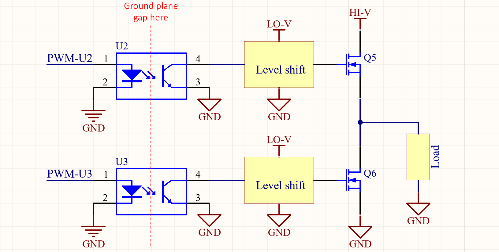
Figure 1. High-voltage half-bridge gate driver. As shown, a conventional approach to implementing this function uses an optocoupler for isolation, followed by a high-voltage gate-driver IC. A potential drawback of this circuit is that the single isolated input channel relies on the high-voltage driver circuit for the needed channel-to-channel.
Introducing the new Matrix TSL dual full bridge motor driver Eblock Matrix Blog

Most of the current sensorless control schemes for BLDC (Brushless DC) motor are based on full-bridge driver. However, half-bridge driver draws a lot of attention due to its simpler structure, smaller occupied volume, lower power loss, easier control scheme and lower production cost, and it has been successfully utilized in several applications. Inspired by these applications, this paper.
What Is Motor Driver Circuit Diagram Circuit

The equation for C C2 is similar to the one identified for direct coupled gate drive circuit. The ripple has two components: one is related to the total gate charge of the main MOSFET and a second component due to the current flowing in the gate pull down resistor: Q G V DRC -VDC2,FW × DMAX. C C2 = +.
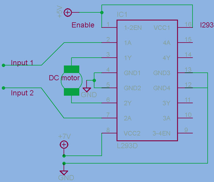
H Bridge Motor Control Circuit Using L293D IC
The circuit is pretty simple, but I'm having some difficulty to turn the power mirror motors with my microcontroller. It needs to be a Half H-Bridge kind of circuit for powering the motors because each motor pin needs three states: VCC (+12V), GND and high impedance (opened). In that case, I'm having two outputs of the microcontroller for each.
Principle schematic of a half bridge driving an inductive load. Download Scientific Diagram

An H-bridge is an electronic circuit that switches the polarity of a voltage applied to a load. These circuits are often used in robotics and other applications to allow DC motors to run forwards or backwards. The name is derived from its common schematic diagram representation, with four switching elements configured as the branches of a letter "H" and the load connected as the cross-bar.
Semiconductors & Actives Electronic Components & Semiconductors Microcontrollers & Programmers
The Half-Bridge Driver block provides an abstracted representation of an integrated circuit for driving MOSFET and IGBT half-bridges. The block models input hysteresis, propagation delay, and turn-on/turn-off dynamics. Unless modeling a gate driver circuit explicitly, always use this block or the Gate Driver block to set gate-source voltage on.
Half bridge circuit motor controller using only 555 ic YouTube

The H-Bridge Motor Driver Circuit. This circuit is called H-bridge because the MOSFETs form the two vertical strokes and the motor forms the horizontal stroke of the alphabet 'H'. It is the simple and elegant solution to all motor driving problems. The direction can be changed easily and the speed can be controlled.
H bridge DC Motor control Bipolar drive Unipolar Drive H bridge Motor driver using MOSFET

Mar 21, 2022 at 17:02. @Darius Half-Bridge driver that can power an absolute maximum of 1700 watts, with a continuous rating of 600/700 watts. The maximum current draw is 70 amps (as stipulated by a 70 amp fuse). The 24V coming from two YUASA car batteries that are lead acid. The PWM is coming from an esp32.
HBridge Motor Driver Circuit L293D, 52 OFF

H-bridge Circuit containing 4 switching elements + 4 catch diodes. Quadruple half-h bridge driver L298 - Dual full-bridge driver. L298 Pin Functions 29. SN754410 Timing Diagram 30. L298 Timing Delays 31. Things to consider when choosing an H-bridge Needed input voltage for motor - determines motor speed Needed input current for motor.
Explanation of Half Bridge YouTube
Control the turn-on and turn-off times of the FETs. Drive circuits can come in many shape or form. There are low-side drivers, that are designed to drive Q2 or Q4 on our bridge. High-side drivers in turn are designed to drive Q1 or Q3. Half-bridge drivers combine one low- and one high-side driver, so they can drive Q1 and Q2 (or Q3 and Q4.
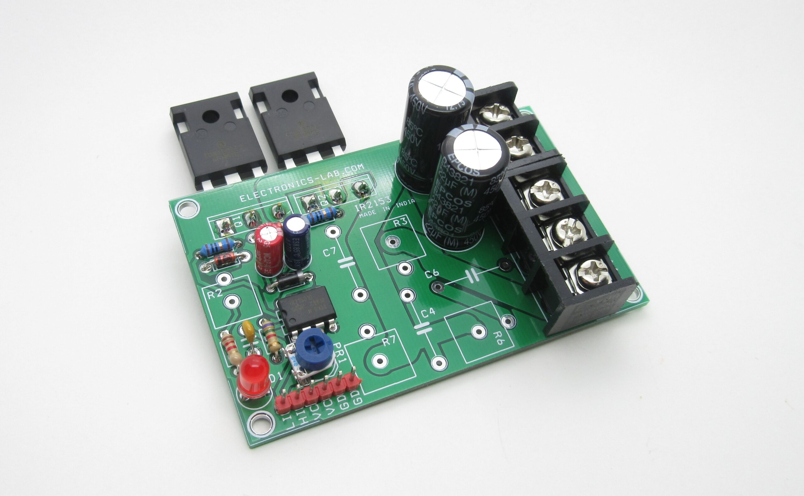
High VoltageCurrent Half Bridge Driver Using IR2153 & IGBT
The H-bridge described in this write-up is capable of currents up to about 40A at 24V, but requires the assembly of a PCB. In the circuit diagram we see that the 4 mosfets surrounding the motor form an "H" shape. The mosfets are used as switches and are activated in diagonal pairs. To apply a forward voltage across the motor, mosfets 1=4=on.
20Amps HBridge DC Motor Driver with Current and Fault Feedback Using IR2104IR2101 IRFP4468

Updated 31st October 2023. Our controllers use either a full bridge or a half bridge PWM circuit to to control the speed of an electric motor. In the half bridge configuration two sets of MOSFETS are connected across the battery, as shown in the diagram below. The drive MOSFET switches rapidly on and off in a series of pulses 20kHz.
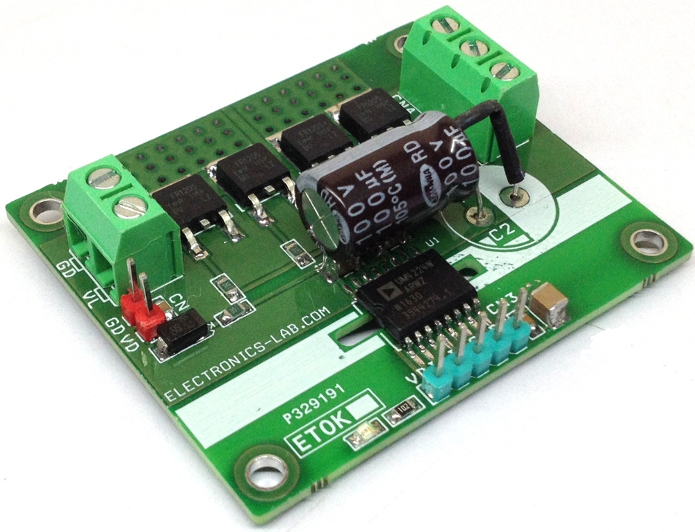
15A 100V Isolated HalfBridge Driver

Short-Circuit Protection in Bridge Applications. The LT1158 protects the top power MOSFET from output shorts to ground, or in a full bridge application, shorts across the load. Both standard 3-lead MOSFETs and cur-rent-sensing 5-lead MOSFETs can be protected. The bottom MOSFET is not protected from shorts to supply.
High VoltageCurrent Half Bridge Driver Using IR2153 & IGBT ElectronicsLab
Infineon's gate driver IC solutions are the expert's choice. We offer half bridge gate drivers with two interlocked channels. Now including the new 650 V half bridge silicon on insulator (SOI) gate driver ICs with high current (2.5 A) and low current (0.7 A) option. With excellent ruggedness and noise immunity, these gate drivers are perfect for motor drives, home appliance, SMPS, battery.
Halfbridge Isolated DCDC Converter Design
The circuit diagram below shows a full-bridge driver IC with four MOSFETs used as the switching element in a LLC resonant converter. In this system, the full-bridge driver's job is to amplify a PWM signal and use this to switch the four transistors ON and OFF; only two transistors are on at a given time. In this topology, on the primary coil.
.
 YouTube")
